Design for Manufacturing
Design for Manufacturing (DFM) in Plastic Injection Molding – A Comprehensive Guide
The Goal of Design for Manufacturing
In the plastics industry, Design for Manufacturing (DFM) blends art, science, and technology to produce a plastic part or product designed prior to tooling and production that meets customer expectations for quality and cost. The goal of DFM is to deliver higher customer satisfaction, reduced production costs, and increased profits.
To reach its goals, DFM requires collaboration between the molder, OEM, and customer. It must leverage best-in-class manufacturing processes. Its principles drive a scientific molding process that includes material selection. DFM also needs to recognize and operate within the maximum performance capabilities of the molder’s manufacturing equipment. It must utilize cutting-edge technology, such as simulation tools and enterprise resource planning software in the design process, as well as robotics and process control systems for manufacturing.
On this page, Rosti explores DFM to help our customers and prospects understand its role during the design validation process, before tooling begins. You can download this entire page as a PDF here, read all our insights and observations by scrolling down this page, or click any of the links above to jump to a topic of interest.
The Basics and Benefits of Design for Manufacturing
Design for Manufacturing (DFM) involves designing a product that optimizes manufacturing efficiencies for the equipment and/or process used in its production so you can achieve the lowest possible unit costs at the highest possible quality. The main reason to integrate DFM into producing a plastic injection molded product is that 70% of its manufacturing costs are determined by design decisions.
DFM requires choosing the right manufacturing process for a part or product, investing in different technologies, using cutting-edge design principles (discussed below), and selecting the right materials with the right properties to deliver the consistency and quality your customers and prospects require.
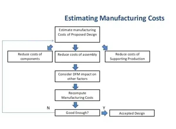
DFM is an essential part of another customer demand: lowering manufacturing and assembly costs. A simple look at how this is achieved is shown below; however, when a DFM plan is completed at the desk, it should be an engineering document laser-focused on achieving exactly the right balance between quality and cost.
13 Design for Manufacturing Guidelines for Reducing the Costs and Challenges of Manufacturing a Plastic Component
Navigating the complexities of manufacturing plastic components can be challenging, full of difficulties and high costs. However, using solid design for manufacturing (DFM) principles can greatly simplify the process and cut expenses. Here are 13 strategic DFM guidelines, designed for plastic component production, to help you overcome challenges, lower costs, and streamline your manufacturing process.
DFM in plastic injection molding reduces costs and time to market
Applying DFM principles in plastic injection molding from the very beginning not only cuts costs but also speeds up time to market. Starting DFM early, even before tooling begins, lets you identify potential design issues and save both time and resources.
Bring everyone to the table to challenge the design
Creating a successful product takes an interdisciplinary approach. That means bringing together engineers, designers, contract manufacturers, mold builders, and material suppliers. Every party offers a unique perspective, and their combined input can help review and refine the design for easier manufacturing.
Design to reduce the total number of parts
Each component added to a design increases complexity and cost. By optimizing your design to reduce the total number of parts, you can significantly simplify manufacturing and save on both materials and labor costs.
Build it with a modular design
Modular design supports flexibility as well as easy assembly, repair, and upgrades. It allows for interchangeable parts, speeds up production, and lowers overall manufacturing costs.
Limit the number of machine operations needed
Every machine operation is a chance for error and increases costs. By efficiently designing to limit the number of machine operations, you can improve production, reduce waste, and minimize downtime.
Use standard components
Standard components are widely available, less expensive, and don’t require custom manufacturing. Using them in your design can dramatically cut costs and make assembly and maintenance easier.
Design parts to be multi-functional
Multi-functional parts can perform more than one job, which reduces the number of components required in a design. This strategy not only streamlines manufacturing but also adds value and functionality to your product.
Design parts for multi-use
Parts designed for multiple uses can be used across different product lines, increasing manufacturing efficiency and lowering inventory costs. This principle also helps create more sustainable designs by cutting down on waste.
Design for ease of fabrication
Making fabrication as easy as possible should be a major goal during design. Simple shapes and designs are less costly to make, require fewer machine operations, and are less likely to result in manufacturing errors.
Avoid separate fasteners
Separate fasteners add complexity to assembly and increase costs. Designing parts to interlock or snap together can simplify assembly and reduce the number of extra components needed.
Minimize assembly directions
Reducing the number of directions needed for assembly can make the process easier, lower the risk of errors, and decrease costs. This tactic also increases the speed and efficiency of your production line.
Maximize compliance
Meeting industry standards and regulations is vital in manufacturing. A design that naturally complies with these standards streamlines production, lowers the risk of non-compliance penalties, and boosts your product’s market acceptance.
Minimize handling and consider how a design impacts the packaging and shipping of parts
Every step in handling, packaging, and shipping adds to costs and increases the risk of damage. Streamlining handling and thinking about how your design affects packaging and shipping can create major cost savings and improve overall quality.
Estimating Manufacturing Costs
Why Design for Manufacturing is Important for the Injection Molding Process
Besides estimating manufacturing costs, your injection molder should use DFM principles to lower component costs, assembly costs, and production support costs, and to identify how DFM decisions affect other factors throughout the entire design and production process.
Another important reason to choose a molder that uses DFM principles is the increasing complexity of plastic injection molded parts. Factors such as tolerance, draft angles, undercuts, and more must be considered during design to meet customer requirements for quality and cost.
Benefits of Design for Manufacturing for Plastic Injection Molding
Lower Production Cost
Design for Manufacturing (DFM) can significantly lower the production costs of plastic components. At Plastic Components Inc., design engineers take advantage of DFM in injection molding to ensure cost-effectiveness and efficiency.
Higher Quality
By focusing on DFM from the very beginning of a project, manufacturers can improve the quality of the final product. This ensures every aspect of the design is optimized for the injection molding process, resulting in fewer defects and overall higher quality.
Quicker Time to Market
DFM streamlines the production process by removing unnecessary steps and inefficiencies. This can greatly reduce the time it takes to move a product from design to market, giving manufacturers a competitive advantage.
Lower Capital Equipment Cost
Optimizing the design for manufacturing allows DFM to reduce the need for specialized machines and tools. This leads to lower capital equipment costs and a more economical production process.
Greater Automation Potential
DFM principles unlock greater potential for automation in manufacturing. Designs that are optimized for automation can cut production costs, boost efficiency, and ensure more consistent product quality.
Bring Production up to Speed Sooner
Through eliminating potential production issues during design, DFM allows for a smoother transition into full-scale production. This means production can ramp up faster, bringing products to market sooner and improving customer satisfaction.
Fewer Engineering Changes
DFM helps identify and solve potential manufacturing challenges during the design phase. This cuts down on the need for costly and time-consuming engineering changes once production is underway, making manufacturing more efficient and cost-effective.
Lower materials and labor costs
By optimizing designs for efficient and easy production, DFM can generate significant savings in both material and labor costs. This results in a more economical and sustainable production process.
Reduce product development cycle time
DFM can greatly shorten the product development cycle by identifying potential production issues during design. This helps ensure a smooth move into production and brings products to market faster.
Emphasis on standards reduces costs
DFM emphasizes following industry standards and best practices. This not only guarantees the quality and safety of the finished product, but also reduces the costs that come from non-compliance and rework.
Essential Factors in Design for Manufacturing Optimization
Before a mold is created, following best DFM practices for plastic injection molded parts means incorporating the following key elements:
Understanding Material Shrink Rate:
Shrinkage describes the contraction of a molded part as it cools after injection. All materials have unique shrink rates depending on resin family (amorphous vs. crystalline materials), mold design, and processing conditions. Resin may also shrink differently depending on flow direction. As a general rule of thumb, a 10% change in mold temperature can cause a 5% change in initial shrinkage. Additionally, injection pressure directly affects shrinkage rates: higher injection pressure means less shrinkage. View typical mold shrink rates here.
Draft Considerations:
The way features of a part are shaped in a mold determines the required draft. Features formed by blind holes or pockets (such as most bosses, ribs, and posts) should taper thinner as they go into the mold. Surfaces formed by slides may not require draft if the steel separates from the surface before ejection. Consider adding angles or tapers to product features like walls, ribs, posts, and bosses running parallel to the direction the part releases from the mold, which makes ejection easier.
- A draft angle of at least one-half degree is sufficient for most materials. High-heat and exotic resins may need one to two degrees of draft. Add an extra degree for every 0.001 inch of texture depth.
- Draft all surfaces that run parallel to the mold separation direction.
- Angle walls and other features formed in both mold halves to make ejection easier and to keep wall thickness uniform.
Maintaining Uniform Wall Thickness:
Uniform wall thickness throughout a part (when possible) is key to preventing thick areas. Design choices that create non-uniform walls can cause the part to warp when the melted material cools.
If parts of different thickness are needed, make the transitions as smooth as possible to let the material flow evenly inside the mold cavity. This helps guarantee a fully-filled mold and lowers the risk of defects. Rounding or tapering transitions in wall thickness will minimize built-in stresses and the concentration of stress caused by abrupt thickness changes.
Selecting the right wall thickness for your part can have a major impact on manufacturing costs and production speed. The minimum usable wall thickness depends on the size and shape of the part, structural needs, and resin flow characteristics. Injection molded part wall thickness generally ranges from 2mm–4mm (0.080″–0.160″). Thin wall injection molding can produce walls as thin as 0.5mm (0.020″). Work with an experienced injection molder and design engineer to be sure your design and material use proper wall thickness.
Adding Radii to Edges:
Besides the main body of a part, uniform wall thickness is also important at edges and corners. Adding large radii to rounded corners brings many benefits to plastic part design, including less stress concentration and better material flow. Parts with generous radii are usually more affordable, easier to make, stronger, and have a better appearance.
Importance of Ribs:
Many designers assume that thicker walls increase a part’s strength. In reality, overly thick walls can cause warping, sink marks, and other issues. Ribs boost the strength of a part without making its walls thicker. With less material needed, ribs provide a cost-effective way to add strength. For more stiffness, increase the number of ribs rather than their height, and space them at least twice the nominal wall thickness apart.
Consideration of Draft Angle:
The way features are formed in the mold determines the draft type needed. Features shaped with blind holes or pockets (like bosses, ribs, and posts) should narrow as they extend into the mold. Surfaces created by slides may not need draft if the steel pulls away before ejection. Consider adding angles or tapers on walls, ribs, posts, and bosses that are parallel to the direction of mold release to make ejection easier.
Part Finishing:
Surface finish options for plastic injection-molded parts vary depending on the part design and the chemical composition of the material used. Finishing options should be discussed early during the design process, as the selected material can significantly impact the type of finish applied. In cases where a gloss finish is required, material selection is particularly important. When considering additive compounds to achieve a specific surface finish and enhance part quality, it’s essential to partner with an injection molder who works closely with knowledgeable material science professionals.
Considering these factors is fundamental for integrating engineering and manufacturing expertise, so that mistakes can be caught, opportunities for efficiency and cost reduction discovered, and even the feasibility of meeting contract requirements assessed. Typically, your injection molder will thoroughly analyze these factors with your team well before the tooling process starts.
DFM is not a stand-alone guideline or principle when producing plastic injection-molded products or parts. It works together with other design optimization approaches such as designing for functionality, assembly, and sustainability, each of which is discussed further below.
Rosti’s Four-Part Approach to Plastic Part Design for Manufacturing Optimization
Design for Manufacturing |
Design for Manufacturing (DFM) describes the process of designing or engineering a product to reduce its manufacturing costs, allowing potential problems to be resolved during the design phase—which is the most cost-effective stage to address them. There are established guidelines for DFM practices that apply to different manufacturing processes. These define tolerances, rules, and common manufacturing checks specific to DFM. |
Design for Functionality |
Throughout the plastic part design process, it is critical to focus on the functional requirements of the part. Experienced design engineers should provide recommendations on modifications to help ensure the part meets its functional needs, including what the part will be exposed to, chemical or corrosive substances the part must resist, functional cosmetic features, and more. |
Design for Assembly |
Design for Assembly (DFA) is a process where products are designed to be easy to assemble, with the main goal of reducing assembly time and costs. The greatest cost benefits of DFA usually come from reducing the number of parts in an assembly. |
Design for Sustainability |
Design for Sustainability focuses on designing parts with print-to-intent measurement in mind—maintaining tolerances with accurate measurement over time. |
Understanding Materials for Plastic Components and Their Role in Design for Manufacturing
Material selection is a vital part of the DFM process for achieving high quality, low cost, and fast production of plastic injection-molded parts and products. The wide range of available plastics and their properties makes communication between material providers, injection molders, and product manufacturers critically important, as addressing specific needs early in the design process is key to avoiding costly changes later.
Material selection impacts strength and flexibility, temperature resistance, durability, appearance, toughness, lifespan, and, of course, production cost. Other needs can include:
- Agency approvals
- Assembly
- Chemical resistance
- Resin availability
When it comes to choosing the right material, it takes experience, expertise, and discussion to balance all these factors before building a mold and tools. Below you’ll find a discussion guide and a basic overview of materials for use in your DFM strategies and processes.
Discussion Points That Guide Plastic Materials Selection for Injection Molding
Choosing suitable materials is a crucial step in the injection molding process and requires careful consideration of various factors that affect the final product. The selected material must match the product’s intended function, safety standards, environmental conditions, and budget requirements. The following chart highlights the key discussion points to consider when selecting plastics for injection molding. By addressing these factors, manufacturers can ensure they choose the most suitable and cost-effective material for their specific injection molding needs.
| Chemical resistance | Child safety |
| Color | Compliance with FDA standards |
| Compliance with NSF standards | Compliance with REACH standards |
| Compliance with RoHS standards | Dielectric properties |
| Economic or cost constraints | Embossing requirements |
| Environmental conditions | Finish requirements |
| Flexibility | Food safety |
| Heat, flame or burn resistance | Material strength |
| Mechanical conditions | Need for reflectivity or transparency |
| Pressure resistance | Rigidity |
| Shelf life | Weight resistance |
A Basic Guide to Material Selection for Injection Molding
Manufacturers use a wide range of plastics to mold components for products and have increasingly replaced other materials like bronze, stainless steel, aluminum, and ceramics. The most common reasons for using or switching to plastic include a longer overall part lifespan, reduced wear on other product components, faster production speeds, corrosion resistance, and weight reduction. Additionally, companies report an average of 25–50 percent cost savings when converting parts to plastic, which often deliver superior performance features.
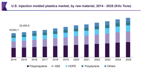
Source: Grandview Research, Injection Molded Plastic Market Report by Raw Material, https://www.grandviewresearch.com/industry-analysis/injection-molded-plastics-market
Working with your injection molding partner to select the best resin early in the design for manufacturability process is crucial to a part’s production success.
Material selection plays a key role in the strength and flexibility of your molded part. Addressing specific needs early in the design process can help you avoid expensive changes later. Balancing features like stiffness, durability, toughness, and other factors is vital to achieving top part performance. It’s also important to understand the main differences among the most commonly used resins.
ABS (acrylonitrile butadiene styrene) is a common injection molding material that can be easily sourced and molded at an affordable price point. It’s a strong, durable material with good impact resistance, is easy to machine, and meets a variety of appearance requirements. However, this resin isn’t suited for parts that will face sustained high heat, as it will warp or melt above or around 200 degrees Fahrenheit.
Polycarbonates are a high-grade group of thermoplastics that are easy to mold and often enhance shatter resistance. Polycarbonate is naturally transparent and ideal for high-strength, glass-like uses (like safety goggles, medical lab equipment, and more). Polycarbonate isn’t well-suited for applications requiring a lot of flexibility or customized colors.
Glass-filled nylon is a reinforced thermoplastic; the base nylon resin is blended with glass fibers to increase strength and heat resistance. This resin is also more electrically nonconductive than many others. However, despite its high melting point, it’s more flammable than some other materials.
Polypropylene is a flexible thermoplastic suitable for both industrial and consumer applications. It’s known for being a highly pliable resin that can be manipulated in many ways without losing its original shape. Polypropylene also offers resistance to solvents, chemicals, and UV rays.
Acetal is known for excellent friction resistance and high rigidity. It can easily be colored and dyed during molding; however, it doesn’t offer outstanding heat resistance.
One of the most important steps in preparing for injection molding resin selection is making a thorough list of requirements for the product’s material selection. This list should definitely include your price target and resin availability, as availability can be a risk factor and backup resin choices should be planned for.
It’s also important to note that some characteristics of high-heat and exotic resins are unique and can perform differently depending on the application. To get the most out of both your design and material choice, experienced design engineers and injection molders need to consider several factors.
Understanding Surface Finishing and Its Role in Design for Manufacturing
When designing a plastic part or product for manufacturing, before building a mold or tooling, discussions and decisions about surface finishing are essential. Conversations about the desired look and performance of the finish will impact the type of material chosen, required additives, and other variables like fill rate, pressure, and temperature tolerances.
During the design stage, the plastic injection molding partner, OEM, and customer should discuss the targeted outcomes for the part or product, including needs such as:
- Allowing trapped gases to escape quickly
- Eliminating plastic flow creases
- Getting better sticker adhesion
- Improving grip
- Improving paint adhesion
- Producing a high polish finish
- Producing a smooth finish
- Producing the highest polish finish
- Removing tooling marks
- Using texture to create undercuts
Like other elements of the DFM approach, surface finishing is part of the cost, quality, and customer satisfaction formula that needs to be addressed at the start of any contract.
Material Finishes
Material finishes play a crucial role in the appearance, function, and durability of injection-molded parts. They can range widely, from a highly glossy finish to a rough textured one, each serving a specific purpose and application. In this guide, we provide a thorough overview of different material finishes, their related SPI standards, methods to achieve them, and typical surface roughness measurements. This information will help you make informed decisions on the right finish for your injection-molded parts to meet both style goals and performance needs.
| Finish | SPI* Standard | Finishing Method | Typical Surface Roughness Ra (μm) |
| Super high glossy finish | A-1 | Grade #3, 6000 Grit Diamond Buff | 0.012 to 0.025 |
| High glossy finish | A-2 | Grade #6, 3000 Grit Diamond Buff | 0.025 to 0.05 |
| Normal glossy finish | A-3 | Grade #15, 1200 Grit Diamond Buff | 0.05 to 0.10 |
| Fine semi-glossy finish | B-1 | 600 Grit Paper | 0.05 to 0.10 |
| Medium semi-glossy finish | B-2 | 400 Grit Paper | 0.10 to 0.15 |
| Normal semi-glossy finish | B-3 | 320 Grit Paper | 0.28 to 0.32 |
| Fine matte finish | C-1 | 600 Grit Stone | 0.35 to 0.40 |
| Medium matte finish | C-2 | 400 Grit Stone | 0.45 to 0.55 |
| Normal matte finish | C-3 | 320 Grit Stone | 0.63 to 0.70 |
| Satin textured finish | D-1 | Dry Blast Glass Bead #11 | 0.80 to 1.00 |
| Dull textured finish | D-2 | Dry Blast #240 Oxide | 1.00 to 2.80 |
| Rough textured finish | D-3 | Dry Blast #24 Oxide | 3.20 to 18.0 |
| As machined | – | Finished to the machinist’s discretion | 3.20 (with visible machining marks) |
Source: K. Varotsis, “Injection Molding SPI Surface Finishes”, Hubs https://www.hubs.com/knowledge-base/injection-molding-spi-surface-finishes/#finishes
Other Plastic Part Finish Options Include:
- Natural Exotic
- Micro Surface Finishes
- Multi-Gloss Patterns
- Graphics
- Leather Grains/Hides
- Woodgrain, Slate, and Cobblestone
- Geometric and Linens
- Images or logos integrated into the pattern
Technology Supporting the Plastic Injection Molding Design for Manufacturing Process
The recent evolution in plastic injection molding has been strongly influenced by the adoption of scientific molding principles and related technologies. The scientific molding approach aims to: (1) reduce development costs and timelines by removing trial and error, (2) create reliable, error-free tooling that avoids costly modifications and improves part quality, and (3) establish a repeatable, auditable manufacturing process. This method strategically integrates technology into every step of production, leading to improved efficiency and quality.
One of the key technologies used in plastic injection molding is simulation software like SOLIDWORKS® Plastics Premium. Widely used in mold flow simulation, SOLIDWORKS allows engineers to predict and solve potential manufacturing issues right at the design stage. This makes it possible to create efficient and cost-effective molds, reducing the need for expensive and time-consuming physical prototyping and iterative changes.
Another crucial aspect of scientific molding is the use of process control systems, especially RJG eDart®. This system monitors and records every variable in the injection molding process, providing real-time data on factors like cavity pressure, temperature, shot size, and screw position. The data generated can be used to identify trends and make parameter adjustments for better performance.
Rosti is a prime example of an organization effectively using RJG eDart in its operations. This process control system plays a key role in maintaining Rosti’s high standards for quality control and production efficiency. With RJG eDart, Rosti monitors and records all variables in the injection molding process in real-time. The collected data—including details such as cavity pressure, temperature, shot size, and screw position—provides a thorough understanding of the production process.
This wealth of data allows Rosti to quickly identify any trends or irregularities, enabling necessary adjustments to keep production parameters optimized. For example, any changes in cavity pressure or temperature might indicate potential issues with the molding process, which can then be addressed before they affect the final product quality. This proactive approach ensures consistent quality control, reduces waste, and boosts production efficiency, putting the principles of scientific molding into practice at Rosti.
To integrate the various technology components, advanced Enterprise Resource Planning (ERP) software like IQMS is used. This software acts as a centralized platform for managing financial and operational activities. By combining simulation software, process control systems, and ERP software, companies like Rosti can ensure their products are consistently high quality and produced cost-effectively. However, for these technologies to be successfully implemented and integrated in the plastic injection molding DFM process, strong communication and collaboration across multiple disciplines are essential.
Advantages of a Scientific Molding Process
Scientific molding is a disciplined, systematic approach to injection molding that is data-driven and focused on delivering high-quality, repeatable results. By applying scientific principles and thorough testing, this method provides a wide range of advantages that improve efficiency and outcomes. From smart materials selection to optimizing part design and tooling, the scientific molding process lets engineers use prior experience and expertise to address unique applications effectively. Plus, the ability to record and analyze data is vital for quality control, offering insights for ongoing part improvement. Here are the key benefits of using a scientific molding process in your manufacturing operations.
- Establishes a data-driven process that delivers repeatable results with minimal variation
- Makes smart materials selection easier
- Enables design engineers to optimize part design for unique applications using previous experience and expertise
- Used to optimize tool design or improve poorly designed tools
- Recorded data is used to assess quality control and make adjustments to improve overall part quality as needed
Design for Manufacturing Case Study: How Rosti China’s Innovative DFM Approach Simplified Sous Vide and Turned a Start-Up into an Award-Winning Global Success

Adopting DFM was critical to designing and successfully producing the intricate device, which needed both top-tier aesthetics and reliable functionality.
A company approached Rosti China with the challenge of designing and manufacturing a cooking device to simplify the sous vide technique for home use. The design required both functionality and premium aesthetics, presenting a complex design and engineering challenge for Rosti China.
Leveraging their expertise in injection molding and knowledge of heat resistance, Rosti China delivered a durable product that could endure long immersion in hot water while also achieving the level of design typically seen in high-end electronics.
Rosti chose a resin with food industry-approved properties and a clean, visually appealing finish. By developing an overmolding technique commonly used in wristwatch manufacturing, Rosti protected the device’s motor, heater, and circuit board inside an extruded tube.
The product saw success in Europe and North America, won an international design award, and ultimately led to the startup’s acquisition by a global home appliance corporation. Rosti China’s ability to deliver exceptional results shows the value of ambitious product design and working closely with experienced industry professionals.
The approach used by Rosti China underscores the important role that DFM can play in a project’s overall success. It cuts production costs and improves manufacturing efficiency, ensuring the final product meets client and end user requirements and expectations.
Summary
Plastics manufacturing is a highly competitive, global industry where companies face both time and cost pressures. Avoiding delays and reducing risks for costly design changes can help your product reach the market faster than your competitors.
The clear line that once separated development and production is now often blurred, with manufacturers relying on industry design experts to get involved in the design for manufacturability process. In fact, manufacturers rank design as the top factor when it comes to reducing overall manufacturing costs.
Over the years, best practices for tooling and part manufacturing have evolved significantly. While production checklists are still crucial parts of the process, the activities earlier in the development cycle are what create real time and budget efficiencies. When a toolmaker or injection molder is brought in early during development, customer goals are understood and unexpected issues can be avoided.
Are you searching for an injection molding partner who can provide expert guidance from design through to final production? Get in touch with Rosti’s knowledgeable team, who specialize in every area of design for manufacturability, development, and production.